SPARTN Corrections via UART
In this example, we will describe how to set up a 3DM-CV7-GNSS/INS to receive L-Band SPARTN corrections from and L-band demodulator. The demodulator we will be using is the Ublox D9S, which is compatible with Ublox's PointPerfect PPP-RTK service. We are using the C101-D9S-0 development board for this example.
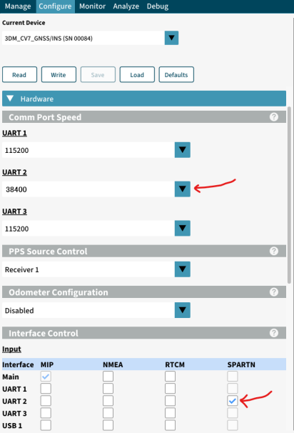
First, we must configure the 3DM-CV7-GNSS/INS to be able to receive SPARTN corrections over its UART_2 port.
-
On a computer with InertialConnect installed, connect your 3DM-CV7-GNSS/INS to the computer with a USB cable.
-
Once connected, navigate to the Configure tab. Under the "Hardware" dropdown, configure the UART 2 baudrate to 38400 baud. Then, check the "SPARTN" box for UART 2 under the "Interface Control" section.
-
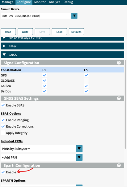
Next, scroll down to the GNSS dropdown. Under the "SPARTN" section, check "Enable SPARTN".
-
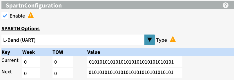
Once enabled, under the "SPARTN Options" dropdown select "L-band (UART)", and enter your keys. The "Week" and "TOW" boxes are that of the expiration date. Each key is a hexadecimal string of 16 non-zero bytes (32 total characters, each 0-9 or A-F).
NOTE: Enabling SPARTN corrections and selecting a source will block any RTCM messages from being received by the device. -
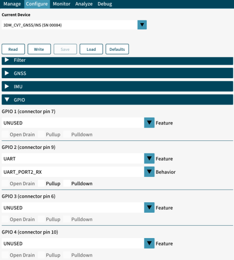
Lastly, configure a GPIO pin to act as a UART receive port for UART 2, and the device will now be ready to receive SPARTN corrections over UART 2.
-
Write the settings to the device, and save them if desired.
Next, the D9S needs to be configured to receive SPARTN data via L-band, and then forward it to the 3DM-CV7-GNSS/INS via UART. U-blox u-center will be required to send configuration strings to the device, instructions for installing u-center can be found in Step 2 of this page of the manual.
-
Open U-center, and connect the D9S to your computer via USB.
-
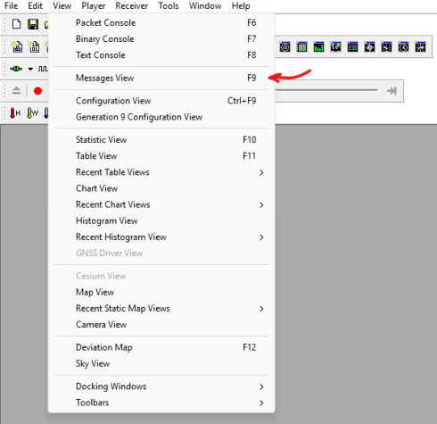
Under the "View" tab, click on "Messages View" to open the messages view window.
-
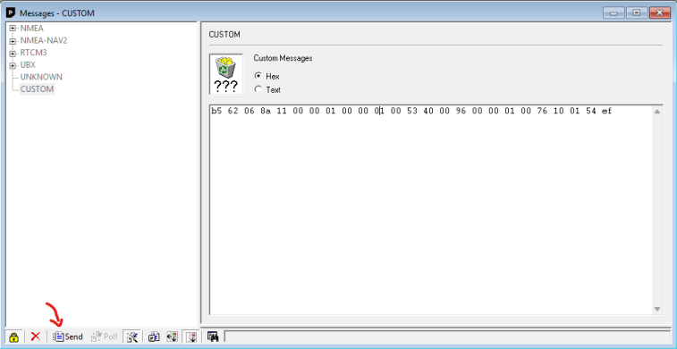
Under the "Custom" section, copy and paste the following two byte strings, and send them to the device. This will configure the D9S to output the required data over the UART 2 port. The settings will be saved to non-volatile memory, so you may unplug the device.
-
b5 62 06 8a 11 00 00 01 00 00 01 00 53 40 00 96 00 00 01 00 76 10 01 54 ef
-
b5 62 06 8a 11 00 00 04 00 00 01 00 53 40 00 96 00 00 01 00 76 10 01 57 1f
-
Finally, connect the TX2 port of the D9S to Pin 9 of the 3DM-CV7-GNSS/INS, and the appropriate power pins.